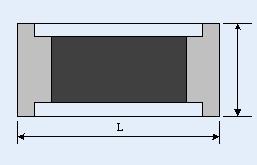
免費加入 | MyRS | 線上客服
泰銘科技股份有限公司
 
  產品介紹分類

Multilayer Ceramic Capacitor (MLCC)(1)
Thin Film Chip Resistor(1)
Metal Strip Chip Resistor(1)

  產品介紹
 

Thin Film Chip Resistor  
 
Thin Film Chip Resistor
   
認證
0
推薦
0


產品介紹

Thin Film Chip Resistor

Dimensions


                                                                                                                                                                            Unit: mm

Size Code

L

W

T

D1

D2

0402

1.00±0.05

0.50±0.05

0.30±0.05

0.20±0.10

0.20±0.10

0603

1.55±0.10

0.80±0.10

0.45±0.10

0.30±0.20

0.30±0.20

0805

2.00±0.15

1.25±0.15

0.55±0.10

0.30±0.20

0.40±0.25

1206

3.05±0.15

1.55±0.15

0.55±0.10

0.42±0.20

0.35±0.25

2010

4.90±0.15

2.40±0.15

0.55±0.10

0.60±0.30

0.50±0.25

2512

6.30±0.15

3.10±0.15

0.55±0.10

0.60±0.30

0.50±0.25


Performance Characteristic

Item

Condition of test

Performance of requirement

Tolerance ≦0.05%

Tolerance>0.05%

Temperature

Coefficient of

Resistance

(According to JIS C 5202 item 5.2)

Measure resistance at +25 as R0, then measure at -55 and +125 respectively as R.

Determine the temperature characteristic of resistance by the following formula.

     T.C.R.= (ppm/)

Where t0=+25 or specified room temperature

 t = -55  or  +125 ± 3

As Specification Table

Short-time

Overload

(According to JIS C 5202 item 5.5)

Apply 2.5 times of rated voltage or maxinum overloading voltage for 5 seconds. Have the specimen stabilized at room temperature for 30 minutes. MeasureΔR/R(%).

ΔR±0.05%

ΔR±0.5%

ΔR±0.5% for high power rating

Dielectric Withstand Voltage

(According to MIL STD 202F Method 301)

Apply maxinum overload voltage for 1 minute.

By Type

Insulation Resistance

(According to MIL STD 202F Method 302)

Apply 100VDC for 1 minute.

1000MΩMin.

Thermal

Shock

(According to MIL STD 202F Method 107G)

In sequence, place the specimen in the chamber at -55 / 25min., 155 / 25 min. as a cycle, The transfer time shall not exceed 5 minutes. After 100 cycles the specimen shall be stabilized at room temperature for one hour minimum and then measure the Δ R/R(%).

ΔR±0.05%

ΔR±0.25%

Load Life

(According to MIL STD 202F Method 108A)

Place the specimen in the oven at 70±2. Apply the rated voltage to the specimen at the 1.5 hours “ON” and 0.5 hour “OFF” cycle. The total time of test is 1000 hours. After the test,have the specimen stabilized at room temperature for one hour minimum and MeasureΔR/R(%).

ΔR±0.05%

ΔR±0.2%

>7kΩ ΔR±0.5%

ΔR±0.5% for high power rating

Humidity

Steady State

According to MIL STD 202F Method 103B)

Place the specimen in the chamber at 40±2, 90~95%RH.

Apply the rated voltage to the specimen at the 1.5 hours “ON” and 0.5 hour “OFF” cycle. The total time of test is 1000 hours. After the test,have the specimen stabilized at room temperature for one hour minimum and MeasureΔR/R(%).

ΔR±0.05%

ΔR±0.3%

ΔR±0.5% for high power rating

Resistance to

Soldering heat

(According to JIS C 5202 item 6.4)

Immerse the specimen in the solder pot at 260 ± 5 for 10 ±1 seconds. Have the specimen stabilized at room temperature for 30 minutes minimum. MeasureΔR/R(%).

ΔR±0.05%

ΔR±0.2%

Low Temperature Operation

(According to JIS C 5202 item 7.1)

Place the specimen in the chamber at -65±2 and apply rated

voltage for 45 minutes and 15 minutes off. After the test, have

the specimen stabilized at room temperature for 2 hours

minimum and Measure ΔR/R(%).

ΔR±0.05%

ΔR±0.2%

ΔR±0.5% for high power rating

Bending Strength

(According to JIS C 5202 item 6.1)

Mount the specimen on a test board. Slowly apply force till 3mm and be held there for 10 seconds, measure the ΔR/R(%) at this position.

ΔR±0.05%

ΔR±0.2%

Resistance to

Dry Heat

(According to JIS C 5202 item 7.2)

Place the specimen in the oven at 155±2 for 96 hours After the test,have the specimen stabilized at room temperature for

one hour minimum and Measure ΔR/R(%).

ΔR±0.05%

ΔR±0.2%

Solderability

(According to JIS C 5202 item 6.5)

Dipping the specimen in the solder pot at 245±5 for5±1 seconds. (Solder : Sn 96.5 / Ag 3 / Cu 0.5 )

At least 95% coverage

 (245±5, 3sec)


Standard Electrical Specifications

Power Rating

at 70

Operating Temp. Range

Max Operating Voltage

Max Overload Voltage

Resistance Tolerance

Resistance Range

TCR

 (PPM/)

0402

1/16W

-55 ~ +155

25V

50V

±0.10% 

±0.25%

±0.50%

10Ω~200KΩ

±25

±50

0603

1/16W

-55 ~ +155

50V

100V

±0.05%

4.7Ω~150KΩ

±25

±50

±0.10%

±0.25%

±0.50%

4.7Ω~800KΩ

±0.25%

±0.50%

2Ω~4.6Ω

0805

1/10W

-55 ~ +155

100V

200V

±0.05%

4.7Ω~500KΩ

±25

±50

±0.10%

±0.25%

±0.50%

4.7Ω~2MΩ

±0.25%

±0.50%

1Ω~4.6Ω

1206

1/8W

-55 ~ +155

150V

300V

±0.05%

±0.10% 

±0.25%

±0.50%

4.7Ω~1MΩ

±25

±50

2010

1/4W

2512

1/2W

±0.25%

±0.50%

1Ω~4.6Ω

1MΩ~2MΩ

Max. working voltage is determined by  or Max. working voltage listed above, whichever is lower.


Low TCR Electrical Specifications

Power Rating

at 70

Operating Temp. Range

Max Operating Voltage

Max Overload Voltage

Resistance Tolerance

Resistance Range

TCR

 (PPM/)

0402

1/16W

-55 ~ +155

25V

50V

±0.10% 

±0.25%

±0.50%

49.9Ω~2KΩ

±5

49.9Ω~12KΩ

±10

±15

0603

1/16W

-55 ~ +155

50V

100V

±0.01%

±0.05%

±0.10%

49.9Ω~8KΩ

±5

25Ω~100KΩ

±10

±15

±0.10%

4.7Ω~332KΩ

±10

0805

1/10W

-55 ~ +155

100V

200V

±0.01%

±0.05%

±0.10%

49.9Ω~16KΩ

±5

25Ω~200KΩ

±10

±15

±0.05%

±0.10%

4.7Ω~500KΩ

±10

1206

1/8W

-55 ~ +155

150V

300V

±0.01%

±0.05%

±0.10%

49.9Ω~30KΩ

±5

25Ω~500KΩ

±10

±15

±0.10%

4.7Ω~1MΩ

±10

2010

1/4W

-55 ~ +155

150V

300V

±0.01%

±0.05%

±0.10%

49.9Ω~30KΩ

±5

25Ω~500KΩ

±10

±15

±0.10%

4.7Ω~1MΩ

±10

2512

1/2W

-55 ~ +155

150V

300V

±0.01%

±0.05%

±0.10%

49.9Ω~50KΩ

±5

25Ω~500KΩ

±10

±15

±0.10%

4.7Ω~1MΩ

±10

Max. working voltage is determined by  or Max. working voltage listed above, whichever is lower.


Derating curve

Power rating or current rating is in the case based on continuous full-load at ambient temperature of 70. for operation at ambient temperature in excess of 80, the load should be derated in accordance with figure of Derating Curve


Packaging

1) Paper Tape Specifications


                                                                                                                                                                                  Unit: mm

Size Code

A

B

W

E

F

P0

P1

P2

ψD0

T

0402

0.70±0.05

1.16±0.05

8.00±0.10

1.75±0.05

3.5±0.05

4.00±0.10

2.00±0.05

2.00±0.05

1.55±0.05

0.40±0.03

0603

1.10±0.05

1.90±0.05

8.00±0.10

1.75±0.05

3.5±0.05

4.00±0.10

4.00±0.10

2.00±0.05

1.55±0.05

0.60±0.03

0805

1.60±0.05

2.37±0.05

8.00±0.10

1.75±0.05

3.5±0.05

4.00±0.10

4.00±0.10

2.00±0.05

1.55±0.05

0.75±0.05

1206

2.00±0.05

3.55±0.05

8.00±0.10

1.75±0.05

3.5±0.05

4.00±0.10

4.00±0.10

2.00±0.05

1.55±0.05

0.75±0.05


2) Emboss Plastic Tape Specifications


                                                                                                                                                                                 Unit: mm

Size Code

A

B

W

E

F

P0

P1

P2

ψD0

T

2010

2.85±0.10

5.45±0.10

12.0±0.10

1.75±0.10

5.5±0.05

4.00±0.05

4.00±0.10

2.00±0.05

1.50+0.10

1.00±0.20

2512

3.40±0.10

6.65±0.10

12.0±0.10

1.75±0.10

5.5±0.05

4.00±0.05

4.00±0.10

2.00±0.05

1.50+0.10

1.00±0.20


  相關產品
LED六菱花園燈
ingot
LED扁四線彩虹燈
五線大美耐


里揚電子商務有限公司
©2007-2024 RecycleSources All Rights Reserved.


(0)
目前尚無任何資料