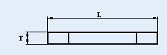
Metal Strip Chip Resistor
Dimension
 
|
Size Code
|
Resistance (mW)
|
Coating
|
L (mm)
|
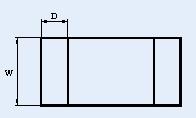
W (mm)
|
T (mm)
|
D (mm)
|
|
2512
|
0.5 to 0.75
|
Green
|
6.35±0.25
|
3.18±0.35
|
1.00±0.20
|
1.93±0.75
|
|
2512
|
1.0 to 20
|
Green
|
6.35±0.25
|
3.18±0.35
|
0.60±0.20
|
1.93±0.75
|
|
2512
|
0.50
|
Black
|
6.35±0.25
|
3.18±0.25
|
1.40±0.20
|
1.30±0.30
|
|
2512
|
0.75
|
Black
|
6.35±0.25
|
3.18±0.25
|
1.00±0.20
|
1.30±0.30
|
|
2512
|
1.00
|
Black
|
6.35±0.25
|
3.18±0.25
|
0.80±0.20
|
1.30±0.30
|
|
2512
|
1.50
|
Black
|
6.35±0.25
|
3.18±0.25
|
0.65±0.20
|
1.30±0.30
|
|
2512
|
2.00
|
Black
|
6.35±0.25
|
3.18±0.25
|
0.50±0.20
|
1.30±0.30
|
|
2512
|
2.50
|
Black
|
6.35±0.25
|
3.18±0.25
|
1.00±0.20
|
1.30±0.30
|
|
2512
|
3.00
|
Black
|
6.35±0.25
|
3.18±0.25
|
0.70±0.20
|
1.30±0.30
|
|
2512
|
3.50
|
Black
|
6.35±0.25
|
3.18±0.25
|
0.71±0.20
|
1.30±0.30
|
|
2512
|
4.00
|
Black
|
6.35±0.25
|
3.18±0.25
|
0.60±0.20
|
1.30±0.30
|
|
2512
|
4.50
|
Black
|
6.35±0.25
|
3.18±0.25
|
0.58±0.20
|
1.30±0.30
|
|
2512
|
5.00
|
Black
|
6.35±0.25
|
3.18±0.25
|
0.50±0.20
|
1.30±0.30
|
|
2512
|
5.50
|
Black
|
6.35±0.25
|
3.18±0.25
|
0.47±0.20
|
1.30±0.30
|
|
2512
|
6.00
|
Black
|
6.35±0.25
|
3.18±0.25
|
0.50±0.20
|
1.30±0.30
|
|
2512
|
6.50
|
Black
|
6.35±0.25
|
3.18±0.25
|
0.47±0.20
|
1.30±0.30
|
|
2512
|
7.00
|
Black
|
6.35±0.25
|
3.18±0.25
|
0.45±0.20
|
1.30±0.30
|
|
2512
|
10.0
|
Black
|
6.50±0.35
|
3.20±0.25
|
0.80±0.15
|
1.90±0.15
|
Performance Characteristic
|
Item
|
Condition of test
|
Performance of requirement
|
|
Black Coating
|
Green Coating
|
|
Temperature
Coefficient of
Resistance
|
Where t0=+25℃or specified room temperature
t = -55℃ or +125℃ ± 3℃
|
As Specification Table
|
|
Short-time
Overload
|
Apply 2.5 times of rated voltage for 5 seconds. Have the specimen stabilized at room temperature for 30 minutes. MeasureΔR/R(%).
|
±0.5%
|
±1%
|
|
Resistance to
Soldering heat
|
Immerse the specimen in the solder pot at 260±5℃
for 10 ±1 seconds. Have the specimen stabilized at room temperature for 30 minutes minimum. MeasureΔR/R(%).
|
±0.5%
|
±1%
|
|
Resistance to
Dry Heat
|
Place the specimen in the oven at 155±2℃ for 96
hours After the test,have the specimen stabilized at
room temperature for one hour minimum.
|
±1%
|
±1%
|
|
Solderability
|
|
At least 95% coverage
(245±5℃, 3sec)
|
|
Thermal
Shock
|
In sequence, place the specimen in the chamber at -55℃ / 25min., 155℃/ 25 min. as a cycle, The transfer time shall not exceed 5 minutes. After 100 cycles the specimen shall be stabilized at room temperature for one hour minimum and then measure the Δ R/R(%).
|
±0.5%
|
±1%
|
|
Load Life
|
Place the specimen in the oven at 70±2℃. Apply the rated voltage to the specimen at the 1.5 hours “ON” and 0.5 hour “OFF” cycle. The total time of test is 1000 hours. After the test,have the specimen stabilized at room temperature for one hour minimum and MeasureΔR/R(%).
|
±1%
|
±1%
|
Standard Electrical Specifications
|

|
Power Rating
at 80℃
|
Operating Temp. Range
|
Resistance Tolerance (±%)
|
Resistance
(mΩ)
|
TCR
(PPM/℃)
|
|
2512
|
|
-55℃ ~ +170℃
|
|
|
50
|
|
2512
|
|
-55℃ ~ +170℃
|
1,3,5
|
|
150
|
|
2512
|
|
-55℃ ~ +170℃
|
1,3,5
|
4.0~5.5
|
100
|
|
2512
|
|
-55℃ ~ +170℃
|
1,3,5
|
6.0~7.0
|
75
|
|
2512
|
|
-55℃ ~ +170℃
|
1,3,5
|
10
|
100
|
|
2512
|
|
-55℃ ~ +170℃
|
1,3,5
|
|
50
|
※ Operating voltage is determined by 
※ Operating current is determined by
High Power Rating Electrical Specifications
|
|
Power Rating
at 80℃
|
Operating Temp. Range
|
Resistance Tolerance (±%)
|
Resistance
(mΩ)
|
TCR
(PPM/℃)
|
|
2512
|
|
-55℃ ~ +170℃
|
|
|
50
|
|
2512
|
|
-55℃ ~ +170℃
|
1,3,5
|
|
50
|
|
2512
|
|
-55℃ ~ +170℃
|
1,3,5
|
|
50
|
|
2512
|
3.0W
|
-55℃ ~ +170℃
|
1,3,5
|
|
75
|
|
2512
|
3.0W
|
-55℃ ~ +170℃
|
1,3,5
|
1.0~2.0
|
50
|
|
2512
|
3.0W
|
-55℃ ~ +170℃
|
1,3,5
|
0.5~0.75
|
100
|
※ Operating voltage is determined by
※ Operating current is determined by
Derating curve
Power rating or current rating is in the case based
on continuous full-load at ambient temperature of
80℃.
For operation at ambient temperature in excess of
80℃, the load should be derated in accordance with
figure of Derating Curve.
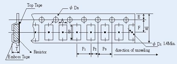
Packaging
Emboss Plastic Tape Specifications

Unit: mm
|
Resistance
(mΩ)
|
A
|
B
|
W
|
E
|
F
|
P0
|
P1
|
P2
|
ψD0
|
T
|
|
0.50
|
3.40±0.1
|
6.70±0.1
|
12.0±0.1
|
1.75±0.1
|
5.5±0.05
|
4.0±0.05
|
4.00±0.1
|
2.0±0.05
|
1.50+0.1
|
1.40±0.1
|
|
0.75
|
3.50±0.1
|
6.80±0.2
|
12.0±0.1
|
1.75±0.1
|
5.5±0.05
|
4.0±0.05
|
4.00±0.1
|
2.0±0.05
|
1.50+0.1
|
1.35±0.1
|
|
1~20
|
3.40±0.1
|
6.70±0.1
|
12.0±0.1
|
1.75±0.1
|
5.5±0.05
|
4.0±0.05
|
4.00±0.1
|
2.0±0.05
|
1.50+0.1
|
0.80±0.1
|
|